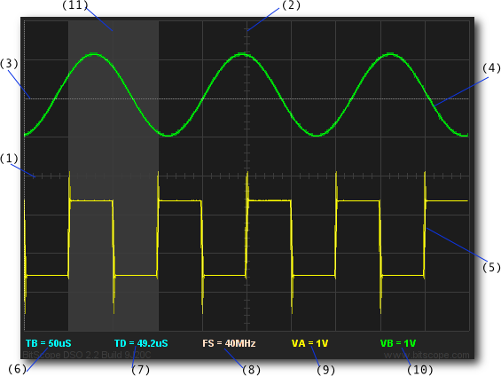
The screenshot above shows a standard dual trace analog WAVEFORM display.
This display format is selected by default when DSO is first powered on. It comprises:
| (1) | X-Axis Graticule | The time axis divided into 10 Divisions. |
| (2) | Y-Axis Graticule | The voltage axis divided into 8 Divisions. |
| (3) | Ground Reference | ChB | The ground (zero) voltage level for Channel B. |
| (4) | Waveform | ChB | A sinusoidal waveform on Channel B. |
| (5) | Waveform | ChA | A square waveform with ringing on edges on Channel A. |
| (6) | Main Timebase | The main timebase (here set to 50uS/Division). |
| (7) | Offset/Delay | The (time) location of the left display edge w.r.t. the trigger. |
| (8) | Sample Rate | The sample rate at which the waveforms were captured. |
| (9) | Voltage Scale | ChA | The Volts/Division for Channel A. |
| (10) | Voltage Scale | ChB | The Volts/Division for Channel B. |
| (11) | Delay Timebase | The current delay timebase setting (optional). |
By default, the timebase zoom is set such that the display shows half of the available capture buffer to make it easy view any feature of the waveform using the waveform offset control.
The WAVEFORM display format shown above is just one of many supported by the DSO.

However, each virtual instrument supports multiple display formats as appropriate for its captured data. For example, logic capture offers timing diagrams or mixed signal displays.
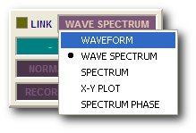
The display format is chosen via the capture control display format widget. Clicking on the widget toggles between the current display and the previous one or right-clicking the widget pops up the instrument's display menu as shown here.
In this example (taken from the SCOPE instrument), the options include WAVEFORM, WAVE SPECTRUM, SPECTRUM, X-Y PLOT and SPECTRUM PHASE.
The display formats supported among the DSO 2.2 virtual instruments are:
| Format | Description |
| WAVEFORM | Time domain analog waveform (digital oscilloscope). |
| SPECTRUM | Frequency domain analog spectrum magnitude (spectrum analyzer). |
| WAVE SPECTRUM | Time and frequency domains combined in one display. |
| SPECTRUM PHASE | Frequency domain spectrum magnitude and phase (spectrum analyzer). |
| X-Y PLOT | X-Y plot (lissajous) of data on Channel A vs B, C and/or D. |
| LOGIC STATE | Logic state (timing) display (8 channels, logic analyzer). |
| WAVE LOGIC | Analog waveform and logic state (timing) display combined. |
| LOGIC VALUE | Logic value (decoded) data display (8 channels, logic analyzer). |
The format selection determines what type of data is shown and the layout of the display. Within each format there are many other parameters that determine how the data is rendered, including the graticule, cursors, phosphor persistence, signal levels, timebase and range and offsets.
Below are some screenshots of some of the more commonly used display formats.
When DSO captures analog and logic signals together, the default is a split analog and logic display.
In this example, the graticule has been turned off and the timing cursors turned on.
| (1) | Analog Display | Up to 4 analog channels are displayed here. |
| (2) | Logic Display | All 8 logic/timing channels are displayed here. |
| (3) | Waveform | ChA | A complex analog waveform on Channel A. |
| (4) | Logic Channel 7 | Timing waveform on logic channel 7. |
| (5) | Logic Channel 0 | Timing waveform on logic channel 0. |
| (6) | Trigger Point | Trigger point (fixed cursor). |
| (7) | Time Cursor | MARK | Absolute (reference) timing cursor (green) |
| (8) | Time Cursor | POINT | Relative (difference) timing cursor (red) |
| (9) | Main Timebase | The main timebase (here set to 50uS/Division). |
| (10) | Offset/Delay | The (time) location of the left display edge w.r.t. the trigger. |
| (11) | Mark Time | Time between the trigger (6) and the MARK (7). |
| (12) | Point Time | Time between the MARK (7) and POINT (8) cursors. |
| (13) | Point Frequency | Frequency implied by the period at (12) |
This display format highlights the use of timing cursors (see cursors for more information).
The timing of the analog and logic waveforms is synchronized so that time measurements can be made between any combination of analog and logic channels. The timing values (associated with cursors) are shown at the bottom of the display to 6 digits precision.
Frequently it is desirable to see a waveform and its associated spectrum together.
This example shows SYDNEY with waveforms and magnitude spectra shown simultaneously.
Like the mixed signal example above, this one also has the graticule disabled and cursors enabled.
| (1) | Spectrum Display | Up to 4 analog channels' magnitude spectra. |
| (2) | Waveform Display | Up to 4 analog channels' waveform display. |
| (3) | Frequency Cursor | MARK | Absolute (reference) frequency cursor (green) |
| (4) | Frequency Cursor | POINT | Relative (difference) frequency cursor (red) |
| (5) | Time Cursor | MARK | Absolute (reference) time cursor (green) |
| (6) | Time Cursor | POINT | Relative (difference) time cursor (red) |
| (7) | Mark Frequency | Frequency of the mark (3) on the first peak. |
| (8) | Point Frequency | Frequency of the waveform (measured in the time domain). |
In this case, the x-axis cursors are not the same; the top pair measure frequency and the bottom pair measure time. The interesting point to note here is that the same property of the signal on channel B (fundamental frequency) is being measured independently in the frequency domain (7) and time domain (8). The result is the same (as one would expect).
Several spectrum display formats are available. This one shows magnitude and phase.
This shows a phase density plot and magnitude spectrum of a pair of related signals.
This screenshot looks a little different to the others because it was taken on a very high resolution display with the DSO maximized to full-screen. Click the image to see it full size.