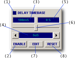
Most virtual instruments have a delay timebase (in addition to their main timebase).
The delay timebase is similar to the main timebase except capture starts after a pre-set delay.
Using the same trigger on a repeating waveform allows the signal to be seen "in overview" (using the main timebase) and a small part of it in fine detail (using the delay timebase).

Timebase zoom can in some circumstances be used instead but the critical difference is that the delay can be set much longer than a single frame (more than 2 hours if required) and DSO can use a different sample rate when delay timebase is active.
For example, one can view an entire video field in the main timebase at one sample rate and zoom in on the (say) 112'th video line using the delay timebase at full resolution at a faster sample rate.
The Delay LED (1) lights up when delay is enabled and ENABLE (2) enabled the delay timebase.
The Delay parameter (3) reports the current delay. The minimum value depends on the BitScope model and is typically 8 uS. For shorter delays, use timebase zoom and waveform offset.
The Delay Timebase parameter (4) sets the delay timebase value in seconds per division.
The Offset parameter (5) reports the waveform offset. The delay plus offset is the total time between the trigger and the left edge of the display (when delay timebase is active).
The offset is adjusted via the waveform offset slider under the main display.
The shuttle control (6) adjusts the delay. This is convenient when viewing a repeating waveform with the delay timebase, as one can scroll dynamically until a feature of interest comes into view.
Alternatively, if a precise delay must be set the EDIT button (7) opens a delay editor which allows a numeric delay time to be entered with up to 8 digits precision. It also allows a precise delay offset to be added the current delay. The RESET (8) button resets delay to the minimum value.
When the main timebase is active and the delay panel enabled, the delay band is displayed to indicate the location of delay timebase region (if it's within the range of the main display).
For example, Fig [1] shows the delay band corresponding to a delay of 50 uS as seen on the display with the main timebase set to 50 uS/Div.
Centered in the delay band in this case is a small glitch appearing at the zero crossing of the falling edge of a sawtooth waveform. Click on this screenshot to see an animated recording of the delay band and timebase being used to "zoom in" on this glitch to examine it in detail.
![Fig [2] - Enabled Delay Timebase Fig [2] - Enabled Delay Timebase](/software/dso/guide/2.2/57.png?m=p)
Enabled Delay Timebase [2]
At the end of the animation (when this glitch fills the display) Fig [2] shows what the delay panel looks like.
The left edge of the zoomed delay timebase waveform display is located 76.17 uS after the trigger. This comprises 50 uS of post-trigger delay and 26.17 uS of waveform offset.
Note that the ENABLE button is down and the delay LED, delay parameter, timebase and waveform offset are all illuminated indicating they are all active.
This measurement could just have easily been done with timebase zoom alone because the delay is very small.
However in practical situations where one would use the delay timebase instead the delay would typically be much larger (for example 500mS in this case).
A common application for the delay timebase is a one-shot mixed/logic capture where some brief event one wishes to see occurs a deterministic but very long time after the trigger event. The delay timebase can also be used to make very precise measurements between two events even if they are minutes or even hours apart.