BitScope usually captures at the highest sample rate available to maximize sample resolution.
However, depending on the timebase, the display sample rate is often lower which allows non-interpolating timebase zoom, resolution enhancement and high bandwidth displays.

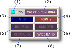
The CAPTURE panel establishes the parameters used to control how BitScope captures and displays waveforms.
Capture LED (1) lights up (in the colour of the trigger channel) whenever DSO talks to BitScope.
Display Format (2) reports (and selects) the data format for the current virtual instrument.
Capture Duration (3) reports the duration of the waveform waveform and the buffer size. It is usually twice the display duration allowing waveform offset.
Sample Rate (4) reports the sample rate used by BitScope during the most recent capture.
Phosphor Mode (5) selects the whether to display a live waveform, an infinite phosphor for accumulating waveform overlays or a finite persistence decay phosphor for eye-patterns etc.
Display Mode (6) selects how the DSO renders waveforms and logic on the display.
Data Recorder (7) controls the integrated waveform data recorder/replayer.
Data Mode (8) defines how the data is (pre)processed by BitScope (if at all).
There are two sample rates managed by the DSO:


The capture sample rate is shown in the capture panel (4) and the display sample rate is shown on the display (as FS =) after the data is captured.
The ratio between them depends on the buffer size, the timebase and timebase zoom.
As the example shows, the capture sample rate (40 MHz) is much higher than the display sample rate (250 kHz). Depending on the data mode both may have the same value but when they're different BitScope applies bandlimited filtering and decimation to maximize display resolution.
For this reason, most DSO virtual instruments use the fastest sample rate available but there are times one might want to choose a particular sample rate or limit the maximum rate; right-click the capture rate (4) to choose from a menu or click the parameter to toggle between two rates.
The duration parameter (3) reports the total capture duration and selects the buffer size.
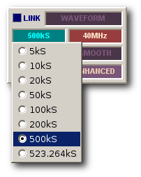
When capturing data it reports the duration (in seconds) but when selected it instead reports the buffer size (in samples).
It is changed by right-clicking the parameter (to pop up the menu) or clicking to toggle between two values. The list of values available depends on the connected BitScope.
The buffer size is maintained per instrument, so selecting a different instrument may change the buffer size.
Which size to use depends on what you want to achieve.
Smaller sizes are best suited when high speed display refresh rates or persistent phosphor displays are desired.
Larger values are better suited to one-shot storage and mixed signal oscilloscope or logic analyzer applications.
For example, typical logic analyzer use works best when the capture buffer is set as large as possible so as much information as possible is captured in a single frame.
Another reason to use a larger buffer size is when looking at very low signal levels or very high bandwidth analog signals. In this case, enhanced or wideband data modes afford the highest sample data precision possible. In some cases an additional 4 bits per analog sample (a total of 12 bits) can be achieved (depends on the BitScope model).
The phosphor mode defines how to accumulate waveforms and logic on the display phosphor.
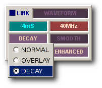
It is changed by clicking the parameter to toggle between values or right-clicking to pop up the menu.
There are three phosphor modes:
In most situations NORMAL mode is used. In this mode the waveform is redrawn every frame.
However, in some display and data modes, accumulating displays can be very useful to view waveform and spectral features not otherwise readily seen.
Examples might include X-Y density plots, clock timing jitter, eye patterns and spectral plots.
The data mode defines how the waveform data is (pre)processed by BitScope (if at all).
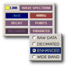
It is changed by clicking the parameter to toggle between two values or right-clicking to pop up the menu.
There are four supported data modes:
To see all the waveform or logic data as actually captured by BitScope, choose Raw Data.
Signal processing is not performed and depending on the buffer size it may be quite slow because a lot of data is sent from BitScope to the PC.
When capturing waveforms for export to a file or for processing by other software, Raw Data is usually the preferred mode because it saves the data as originally captured by BitScope.
It can also be useful when looking for analog glitches or very short duration logic events in one-shot data because every sample captured is shown on the display.
For the fastest repeating display refresh rates choose Decimated but beware of aliases...
BitScope usually captures at sample samples rates much higher the display's sample rate (except when using very fast timebase settings). As a consequence, decimating the data in BitScope before sending it to the PC reduces the link bandwidth for a much faster display refresh rate.
As with any digital sampling oscilloscope, decimation can produce aliases and images of the waveform can appear at the wrong frequency. This may or may not be what is expected and it occurs when frequencies in the signal are higher than 1/2 of the display rate.
When looking at arbitrary analog waveforms and certainly when viewing logic data, aliases are probably undesirable. It's easy to tell whether the waveform is an alias; select Enhanced or WideBand display mode instead and if the waveform changes shape or frequency, Decmiated mode has been showning an alias.
Viewing aliases in Decimate mode is useful when sub-sampling or accumulating X-Y plots or dot displays on persistent phosphor. Using this technique it is possible to view periodic waveforms of frequencies up to the analog bandwidth limit of BitScope (100 MHz) and similar applications (e.g. generating eye patterns for ISI measurements).
For the highest bit-resolution capture with minimal chance of aliases choose Enhanced mode.
Depending on the ratio between the capture and display sample rate, Enhanced mode can improve the bit resolution of captured data (at the display sample rate) by up to 4 bits (for 12 ENOB resolution from an 8 bit BitScope). Like Decimated mode, Enhanced mode is also fast.
Due to the higher bit resolution, Enhanced mode can be very effective when viewing low level signals. It can also significantly enhance spectrum displays, particularly when low level periodic signals are buried in wide band noise (a common situation).
See the quantization noise below for an example of what Enhanced mode can do.
To maximize the potential benefit of Enhanced mode, choose a larger buffer size.
![Fig [1] - High Bandwidth Waveform Display Fig [1] - High Bandwidth Waveform Display](/software/dso/guide/2.2/21.png?m=p)
Fig [1] - High Bandwidth Waveform Display
To see the "full picture" choose WideBand mode.
Like Enhanced mode, WideBand offers high bit-resolution analog waveform display but in addition it simultaneously shows high frequency components (noise or other signals) that may be present on the waveform.
Fig [1] shows a WideBand display of a square wave in the presence of a higher frequency tone burst and a lot of noise. Without this mode aliasing effects would distort the displayed waveform beyond recognition.
Because this type of display is so useful, it is the default for most of the DSO's analog virtual instruments.
For those with experience of high performance analog scope, WideBand should look quite familiar.
The display mode selects how the DSO renders waveforms and logic on the display.
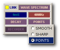
It is changed by clicking to toggle between two values or right-clicking to pop up the menu.
There are three display modes:
Which mode is best depends on which features of a waveform or logic trace one wants to see and data mode.
This is the default and most familiar looking display mode.
Analog waveforms are drawn as curves that fit the sampled analog data and logic traces are drawn as standard high/low line segments.
Implicit in smooth mode is the assumption that the waveform data is sampled real-time (i.e. it's not sub-sampled or equivalent time sampled). It uses bandlimited interpolation to render waveforms, which means that very high frequency real-time waveforms will be shown as approximations.
If higher resolution rendering of high frequencies is required, equivalent time sampling (periodic sub-sampling) should be used. Smooth display mode can accomodate this but points mode on a persistent phosphor will produce higher resolution results.
Smooth spectrum displays are drawn as area filled interpolated curves.
Similar to smooth but drawn without bandlimited interpolation and showing individual samples.
Sharp is a finer display mode (it doubles the display sample rate) and makes precise sample values visible with line segment transitions between them.
Sharp spectrum displays are also double the resolution of smooth. This can be quite useful when more display bandwidth is needed to help identify aliased spectrum components or make more precise frequency or bandwidth measurements.
Points mode plots only the sample points and assumes nothing about the mode of capture.
It is ideal for accumulating X-Y plots or sub-sampled waveform displays and is most useful when used with persistent phosphor. Spectra and logic are rendered the same as sharp mode.
As with any digital oscilloscope, quantization noise is produced when converting analog signals to their digital form. Normally this is not a problem because the quantization noise level is very low compared to the signal itself and can cannot be seen on the display.
However when measuring very low level signals, quantization noise can become significant.
Fig [3] shows a 4 kHz sinusoidal waveform of very low level (50 mV peak-to-peak).
![Fig [3] Small Signal - Raw Data Mode Fig [3] Small Signal - Raw Data Mode](/software/dso/guide/2.2/69.png?m=p)
Fig [3] Small Signal - Raw Data Mode
Even in the most sensitive range the quantization noise is significant for such a small signal. In this case it is about 8mV/quantum and is clearly visible on this Raw Data waveform display because at 50mVp-p this signal uses only the bottom 3 bits of the A/D range (i.e. only 8 digital steps).
Fig [4] shows the same 4 kHz sinusoidal waveform but with Enhanced Data Mode selected.
![Fig [4] Small Signal - Enhanced Data Mode Fig [4] Small Signal - Enhanced Data Mode](/software/dso/guide/2.2/70.png?m=p)
Fig [4] Small Signal - Enhanced Data Mode
The bit-resolution has been increased (by more than 3 effective bits in this case), so the effects of quantization noise are greatly reduced and the waveform is much clearer. The quantization noise as measured in the spectrum analyzer has dropped by about 15dB compared to Raw Data mode.
This huge resolution improvement is done entirely in the digital domain by exploiting oversampling inherent in the high capture sample rate. By using bandlimited filtering and decimation, BitScope is able to extract more than 3 extra bits of resolution from the same 8 bit raw waveform data.
However we can do even better by also enabling an analog prescaler on this channel, Fig [5].
![Fig [5] Small Signal - Enhanced Data Mode + prescaler Fig [5] Small Signal - Enhanced Data + Prescaler](/software/dso/guide/2.2/71.png?m=p)
Fig [5] Small Signal - Enhanced Data + Prescaler
With both the prescaler and enhanced data mode we can now really see the signal for what it is, a pure sinusoid with very low noise, even though it's just 50mVp-p. We have reduced quantization noise a massive 28dB compared the original raw waveform data.
Enhanced data mode filters broadband noise (of which quantization noise is a common source), but it may be desirable to see whether any noise exists in the signal, even though one may also want to see a high quality image of the waveform itself.
In this case, use WideBand Data Mode. Fig [6] shows the same waveform in rendered WideBand.
![Fig [6] Small Signal - WideBand Data Mode Fig [6] Small Signal - WideBand Data Mode](/software/dso/guide/2.2/155.png?m=p)
Fig [6] Small Signal - WideBand Data Mode
Here it is possible to see both the resolution enhanced sinusoidal waveform and the broadband noise at the same time. In practice, if the primary source of noise is quantization, it's probably more useful to use Enhanced mode. Where the noise comes from other sources (details of which you may need to know), WideBand makes it easy to see.