
A unique feature of the DSO is that while its name may imply "Digital Storage Oscilloscope" it is in fact a set of integrated "virtual instruments" that can do far more than an normal oscilloscope.
DSO Version 1.3 supports the following test, measurement and data acquisition instruments:
All of these instruments share access to the BitScope to which the DSO is connected.
They are also integrated with each other to allow comparative measurements to be made between different instruments and different capture modes of each instrument.

The control bar down the right side of the DSO application window is where the instrument, display and global controls are located.
The buttons that appear depend on the BitScope and selected instrument.
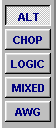
For example, on BS50U the buttons appearing with ALT selected are:
(1) POWER: turns the DSO "on" and "off".
(2) SETUP: BitScope connection preferences.
(3) ALT: ALT capture dual channel mode.
(4) CHOP: CHOP capture dual channel mode.
(5) LOGIC: logic analyzer capture mode.
(6) MIXED: mixed analog/logic capture mode.
(7) AWG: arbitrary waveform generator mode.
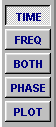
(8) TIME (waveform): waveform display display.
(9) FREQ (frequency): magnitude spectrum display.
(10) BOTH (wave/freq): waveform and spectrum (sppt) display.
(11) PHASE (frequency): magnitude and phase spectrum display.
(12) PLOT (waveform): plot waveform (CHA vs CHB) display.
POWER and SETUP are always present.

POWER: click to "switch on the DSO".
SETUP: click to open the setup dialog.
More information about setup and configuration is available here.
The selected instrument configures the operation of DSO for different types of measurement. Usually you choose the most appropriate instrument as the first step when performing a new measurement.
With BS2xx and BS3xx BitScopes the choices are ALT (alternating capture), CHOP (chopped capture) and MIXED (mixed signal capture).
On BS4xx CHOP and ALT are merged into one instrument (called SCOPE) and on BS5x an additional logic only instrument (called LOGIC) is available.
BitScope models that include a waveform generator also include the AWG instrument.
ALT is usually preferred for single or dual channel high bandwidth analog capture and CHOP for lower bandwidth phase aligned dual channel analog capture
LOGIC is for for high speed logic only capture, MIXED for analog + logic capture, and AWG for waveform generation (and simultaneous waveform capture in the case of BS310).
Below the instrument selectors are the display selectors which vary according to the instrument.
SCOPE, ALT, CHOP and AWG instruments have choices TIME, FREQ, BOTH, PHASE and PLOT.
The MIXED instrument has choices MIXED, LOGIC and TIME.
The display selection is "modal". That is, if you change the selected instrument, the display (and other settings like timebase) most recently selected for that instrument will be restored.
Display selectors do not affect the way data is captured, only how it is presented on the display. They configure the X and Y axes, scaling and measurement units, graticule type, cursors and splits.
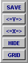
Below the display selectors are several global controls:
SAVE exports the current display image as a bitmap file (BMP).
The resulting graphic may be imported as an image in word documents or encoded as PNG, GIF or JPEG files for use on the web or as email attachments.
The <=X=> and <=Y=> buttons enable the display cursors.
HIDE flips the application between full control and hidden control view.
When the controls are hidden the display expands to occupy the full window.
GRID enables the display graticule.
For regular oscilloscope operation it will normally be enabled. When working with display cursors or when inspecting waveforms in fine details it is often convenient to disable it.